
Laser Marking
Home > Laser Marking
The Application of Dynamic Focusing Scanning System
In the world of scanned laser marking devices, galvo motors move
mirrors that direct a highly focused laser beam onto an x/y plane. These
mirrors move at incredible speeds to scribe text, barcodes, 2D codes, and other
various graphics onto the flat surface of a production line component.
The benefits of
using a laser to perform marking are well known. High-speed, high-quality, and
permanent marking can take the place of slower and less reliable technology
such as pin stamping or inkjets. As long as the intended target is
two-dimensional and stays within the focal range of the laser (typically ±2mm),
then laser markers can provide years of maintenance-free operation. But what if
it’s necessary to laser mark on a surface that is not flat? Or what if there’s
a need to mark on two different flat surfaces that happen to be at different
heights?
For the latter,
when the different heights are the result of a product changeover, the
conventional solution is to mount the laser head on a movable jig. When it
comes time for a product changeover, an operator would mechanically adjust the
height of the jig to some predetermined level. This is somewhat labor
intensive, and can be unreliable as it depends on the experience or skill of
the operator.
Three-axis Control
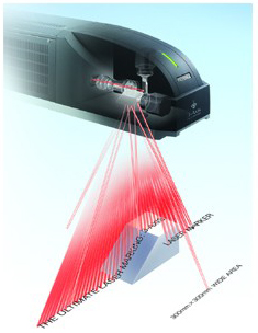
This technology takes existing x/y galvo mirror configurations and applies it to the z-axis. The laser expansion lens, which normally remains fixed at the output point of the laser tube, is placed on a sliding electronic galvo that moves the lens closer or further from the laser output. As the expander moves closer to the laser output, the focal point of the laser does as well. In essence, this creates a z-axis field in which the laser is free to mark any surface that appears within ±21mm of the original focal distance. This added flexibility enables these units to mark a host of previously untouchable surfaces, such as cylinders, spheres, inclined planes, and multi-tiered components, all without a loss in accuracy or speed.
Three-axis control technology offered a solution
that fit perfectly into the needs of this particular application. Because the
Keyence markers are able to adjust their focal point at speeds up to 12,000
mm/s, both tiers could be marked distortion-free at production line speeds.
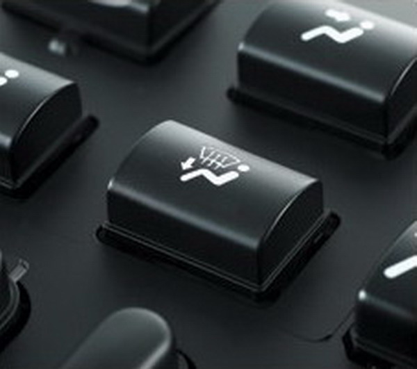
Working with curved buttons
A
similar situation occurred at a large automotive component manufacturer. Many
of us take for granted the buttons we push in our cars on a daily basis: heat,
defrost, A/C, volume up, radio preset. These buttons were traditionally marked
with ink, and over time the most frequently used buttons would show signs of
wear. This automotive supplier wanted a new, more durable method for marking
the various designs on its buttons; lasers seemed to be a natural conclusion.
This idea worked for flat buttons, but many of
the buttons on a console have a slight curve. To fully implement a laser
solution, this company would have to find a way to remove the top layer of
paint from flat surfaces and from the multitude of curved surfaces that are
starting to appear in more ergonomically designed passenger cabins. Initial
solutions included a complex motorized stage to precisely control the height of
the button rack as it moved under the laser. However, this technology proved to
be unreliable and expensive. Quality is of the utmost importance for consumer
products; nobody wants the faceless little guy on his climate control buttons
to have an oblong head.
Marking Builder 3D software offered a combination of simplicity
and precision to achieve a near flawless mark on the curved buttons. To
complete this mark, the laser operator had to carry out three simple steps:
1. Map out the dxf logo files in a 2D layout.
2. Choose “Cylinder” and enter the diameter of the buttons. The
real-time 3D display of the software offered a way for users to verify the
position of all the marks.
3. Upload the settings to the laser head.
With the three steps completed, the MD-V was ready to mark. Figure 3 displays the results of the laser mark; uniform marking quality matched or exceeded that of the inkjet marks.
Wide-area marking and cutting
Other Applications
The three-axis
control described above may have other industrial materials processing
applications, for example, trimming gates on injected molded parts, stripping
large-diameter rubber-sheathed wires, and accurately cutting out large-area
patterns in fabric or thin plastic sheets.
Three-axis control
technology is still very new to the market, and is just starting to inspire
imaginative solutions to problems faced in manufacturing industries across the
board. Increased throughput, accurate marking over large areas, and the ability
to mark on uneven surfaces are just a few ways three-axis lasers can improve
efficiency and reduce costs. The potential opportunities for implementation are
virtually boundless.